Reformatting flow diagrams for explaining complex processes
Part 2 of "Creating a good flow diagram"
Last month, I wrote about creating a good flow diagram to visually explain a process. As I said, you don’t have to learn ISO or UML to create good flow diagrams. But, there’s a complication. What if your processes are very complex with multiple “users” who use different pieces of software/systems? What if you need to combine multiple existing flow diagrams? Do the techniques still work?
What makes some flow diagrams more complex?
Lets define “complex”. Isn’t it just more process boxes and decision trapezoids?
Yes, but there’s three specific aspects that make some processes more difficult to clearly communicate in a flow diagram.
Multiple “users”. Recently, I examined a flow diagram for a healthcare company which included 5 users: consumer, two different internal support teams, two different types of doctors. Communicating who is doing what in the flow diagram increases information complexity.
Multiple “systems”. When a process touches multiple different software applications or systems, communicating which system is used by which user increases information complexity.
Multiple “sub-processes''. Complexity comes from processes that are overly long because it turns out that a long process is actually several independent sub-processes. Take the process of ordering food for delivery in an app. This process can be broken into sub-processes: searching for restaurants, choosing dishes, and making payment, each with its own activities and decisions. Increased complexity in the overall flow diagram is a result from uncovering these sub-processes.
Steps for Formatting Complex Flow Diagrams.
Don’t worry too much day one. If you haven’t created a flow diagram, start with creating a flow diagram. Only worry about this problem when you have multiple users, systems, and sub-processes.
Don’t start with swim lanes. Common wisdom is to lay out some swim lanes if you know your flow diagram will be complex because there are going to be multiple users, systems, and sub-processes? DON’T. Why? Because, while swim lanes are conceptually good for organizing like processes, it adds an unnecessary constraint in the discovery and drawing process. Your job early on is to discover and document the process, not make it beautiful. See formatting tips below for an alternative to swim lanes.
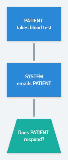
Identify word’s you’ll use to describe each of your “users”. Then capitalize in processes for easy identification. Too often when there are multiple “users” in a flow diagram, people use different words to describe the same user (e.g., customer support, support agent, agent, CSR). Reduce this confusion by deciding what you want to call your “users” and use it consistently to reduce confusion. Then, capitalize these terms throughout your flow diagram for easy identification.
Break processes into sub-processes. Once you start to have a long flow diagram or you have several independent flow diagrams, it’s time to break it down and identify sub-processes.
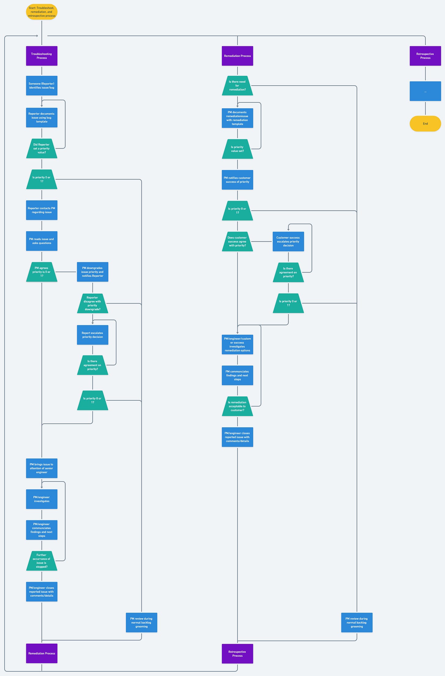
In the example above, you’ll notice that I’ve created 3 sub-processes (each start and end with purple boxes). These sub-processes are self contained within and reusable meaning I can navigate within a sub-process without having to refer to another sub-process. This is the trick to make long processes more manageable and readable. As an actionable tip, when decomposing long flow diagrams into sub-processes, look for a process box where lots of other processes are pointing to it. That’s usually a signal of where to think about dividing into a sub-process.
Evaluate if your process is actually a decision. Put on your editor’s hat and reread the process language. One common issue I see is when a process is written with a condition (e.g., “USER submits within 30 seconds”). The condition, “within 30 seconds” should be separated into a decision symbol.
Use the active tense to describe who is doing the action. Processes can be written in two forms: the person doing the action or the person receiving the action. For example, you can write “SUPPORT sends email to CUSTOMER” or "CUSTOMER receives email from SUPPORT”. Always better to describe who is doing the action (e.g., SUPPORT sends email to CUSTOMER). It’s more clear who needs to perform the process. It’s also easier to write the next process (e.g., “CUSTOMER reads email from SUPPORT”).
Use colors instead of swim lanes. In complex flow diagrams, I find swim lanes sometimes very difficult to use and maintain. The extra lines that divide swim lanes adds unnecessary clutter. Making sure the symbols fit into a swim lane is a lot of work. While swim lanes works well for simple flow diagrams, I think it’s better to use clear “user” labels (#2) and colors.
Final Thoughts
It’s all about formatting. As you might have noticed, all the advice here is focused on formatting. The fundamentals are the same whether your flow diagrams are short or long.
Good formatting takes time. A run of thumb I’ve developed is that formatting complex flow diagrams typically take 4-8 hours, broken over 2 days. Like editing, you need breaks, to step away from the flow diagram before re-examining it. This isn’t something you can rush through in one hour if you want to make the document easy to understand for others.
People who are familiar with the “old” flow diagrams will react negatively to changes. As you reformat and clean up complex flow diagrams, people who have read, worked on, or are familiar with “old” flow diagrams will dislike any changes. This is because they have to re-learn something (i.e., extra work). So, if you don’t need to share your complex flow diagram with others, then you don’t need to reformat. However, a true test of whether the effort is worthwhile is providing the reformatted flow diagram to new employees or coworkers who just joined the project and evaluate against the three principles for flow diagrams: make information comprehension easy for people, use fewer symbols so it’s easy to update, and be tool agnostics.
Assign the word “SYSTEM” or equivalent as an “user” for software events triggered automatically. In #2 above, I say, “Identify word’s you’ll use to describe each of your “users”. Use the word SYSTEM when the process is automatically triggered by software. You can then color code different SYSTEM process symbols to identify which SYSTEM is triggering what process.
Do you have a complex flow diagram? Leave a comment below and I’m happy to help you apply the above techniques to make it better. And if you’ve enjoyed the read, answer 5 questions for feedback.]


